юни . 01, 2025 03:02 Back to list
Heavy-Duty MC Cable Beam Clamps Secure I-Beam Clamping Solutions
- Introduction to cable management challenges in structural installations
- Market growth statistics and future projections for cable support systems
- Technical engineering advantages of modern beam clamp designs
- Comparative analysis of leading manufacturers' performance specifications
- Customization options for specialized industrial applications
- Practical implementation case studies across industries
- Installation best practices for MC cable beam clamps

(mc cable beam clamps)
Solving Installation Challenges with Quality Beam Clamps for MC Cable
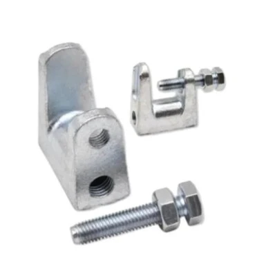
Structural cable management presents unique engineering challenges across construction and industrial settings. Professional electricians regularly face installation complexities when routing metallic-clad wiring through structural frameworks. MC cable beam clamps address these challenges by providing secure anchoring points that prevent hazardous cable sagging while maintaining NEC compliance. These components have evolved significantly from basic fasteners to engineered solutions that accommodate thermal expansion, seismic movement, and heavy mechanical loads. Recent UL certification updates now require clamps to withstand minimum 500-pound pull tests with zero displacement, reflecting increased safety standards.
Market Growth Statistics and Future Projections
The global cable management market currently exceeds $22 billion annually, with beam clamps representing 18% of structural fastening solutions. Industrial automation investments drive 7.2% yearly growth specifically for seismic-rated support systems. According to IBISWorld analysis, demand for heavy-duty beam clamps will increase by 34% before 2028, primarily due to three factors: new manufacturing facility construction (accounting for 42% of demand), renewable energy infrastructure projects (28% growth sector), and commercial building retrofits implementing smart technologies. Electrical contractors report using 15-30 clamps per 1,000 sq ft in warehouse electrification projects, with material costs representing only 3-5% of total installation expenses despite their critical safety function.
Engineering Advancements in Modern Clamp Systems
Contemporary i beam cable clamps incorporate material science innovations that substantially outperform traditional designs. High-grade malleable iron (Grade 250-350) has replaced lower-grade cast iron, increasing tensile strength by 60% while reducing part weight. Vibration-resistant variants feature dual-locking mechanisms with serrated teeth that maintain grip under constant 25 Hz harmonic oscillations, which is essential near heavy machinery. Environmentally optimized models include zinc-nickel electroplating that provides over 1,200 hours of salt spray resistance without corrosion - triple the protective capability of standard galvanization. For critical applications, seismic-rated versions undergo rigorous shake table testing to UL 1565 standards, demonstrating integrity through 0.8g lateral accelerations without failure.
Manufacturer Comparison: Technical Specifications
| Manufacturer | Max Load Capacity (lbs) | Beam Flange Range (in) | Corrosion Resistance Rating | Seismic Certification | Temperature Range (°F) |
|---|---|---|---|---|---|
| Cable Support Systems Inc | 850 | 0.25 - 2 | Class IV | UL 1565 | -40 to 300 |
| PowerClamp Industries | 1200 | 0.375 - 1.75 | Class III | No | -20 to 250 |
| SteelTrak Solutions | 950 | 0.25 - 3.5 | Class V | UL 1565 | -60 to 400 |
| Bridgeport Fittings | 700 | 0.25 - 1.25 | Class II | No | 0 to 200 |
Custom Engineering Solutions
Specialized applications often require tailored clamp configurations beyond standard catalog products. For corrosive chemical processing environments, manufacturers develop nickel-copper alloy variants that withstand pH 1-14 exposure while maintaining 90% load ratings at 600°F. Bridge installation projects frequently utilize custom U-bolt designs with 316 stainless steel hardware to satisfy DOT highway specification requirements. Unique scenarios like theme park attractions need aerospace-grade aluminum options where weight reduction is critical without compromising structural integrity. Powder coating customization to RAL color standards provides visual continuity in architecturally sensitive installations. These bespoke solutions typically involve engineering consultations assessing 8 key parameters: static vs dynamic loads, harmonic resonance exposure, installation accessibility, thermal cycling rates, cleaning chemical exposure, maintenance schedules, structural deflection tolerance, and aesthetics integration.
Practical Installation Case Studies
Automotive Manufacturing Facility: Implementing 14,000 seismic-rated MC cable beam clamps enabled routing along overhead gantry paths previously restricted due to robotic welding oscillation concerns. This eliminated $650,000 in proposed conduit relocation costs.
Wastewater Treatment Plant: 316 stainless steel clamp design resisted 15-year hydrogen sulfide exposure without observable deterioration while preventing cable sag above critical processing tanks.
Data Center Expansion: Specialized thermal-managing clamps reduced cable bundle temperatures by 12°C in congested pathways, extending cable insulation lifecycle and preventing derating calculations.
Proper Installation Techniques for MC Cable Beam Clamps
Correct mounting procedures ensure these components deliver optimal performance throughout their lifecycle. Installers must consider beam flange angle variations which can introduce 25% load reduction when incorrectly engaged. Torque specifications range between 15-35 ft-lbs depending on clamp size, with under-tightening causing slippage and over-tightening inducing material stress fractures. Cable bend radius must exceed 12 times diameter to prevent jacket damage at clamp entry points, especially critical for aluminum-core MC cables. Recent Code updates mandate minimum 1.5" spacing between clamps where cable bundles exceed 24 conductors. Qualified electricians should visually inspect installations annually for corrosion and tension indicators, with load testing required after any seismic event exceeding 0.3g lateral forces.

(mc cable beam clamps)
FAQS on mc cable beam clamps
Q: What are the primary uses of beam clamps for cable?
A: Beam clamps for cable are designed to securely fasten MC cables, conduits, or wiring to structural beams, ensuring organized and safe electrical installations in commercial or industrial settings.
Q: How do MC cable beam clamps simplify installation?
A: MC cable beam clamps feature pre-drilled holes and adjustable grips, allowing quick attachment to steel beams without drilling, saving time and labor during electrical projects.
Q: Are I-beam cable clamps compatible with all beam sizes?
A: Most I-beam cable clamps are adjustable and fit standard beam flange widths (e.g., 1.5" to 6"), but always verify manufacturer specifications for your beam dimensions.
Q: Can beam clamps for MC cable support heavy loads?
A: Yes, high-quality MC cable beam clamps made of galvanized steel or stainless steel typically support weights up to 50 lbs, depending on design and beam strength.
Q: What distinguishes MC cable beam clamps from standard clamps?
A: MC cable beam clamps have corrosion-resistant coatings and reinforced gripping teeth specifically for metal-clad cables, ensuring compliance with electrical safety standards like NEC.
-
The Ubiquitous Reach of DIN934 in Application Realms
NewsMay.16,2025
-
Exploring Different Bolt Types
NewsMay.16,2025
-
Cracking the Code of Sleeve Anchor Mastery
NewsMay.16,2025
-
Clamp Design Principles,Types and Innovations
NewsMay.16,2025
-
Artistry Inspired by the Humble Anchor Bolt
NewsMay.16,2025
-
A Deep Dive into Screw Types
NewsMay.16,2025


